 Checking the drawing
|
Command |
Path |
|
Check Drawing |
ConnectCAD > Drawing Document context menu |
Vectorworks can automatically check the drawing (the current layer or all layers) for problems with sockets, circuits, devices, signals, and layout objects. Any issues can be color coded for easy identification.
To check the drawing:
Select the command.
The Check Drawing dialog box opens.
Click to show/hide the parameters.Click to show/hide the parameters.
|
Parameter |
Description |
|
Sockets |
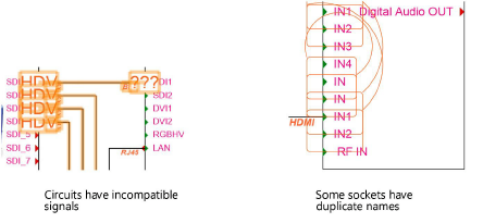
Checks for duplicate socket names and duplicate instances of jackfield holes |
|
Devices |
Checks for duplicate device names |
|
Circuits |
Checks for duplicate circuit names and deleted or moved circuits |
|
Signals |
Verifies whether the signal type is the same between the connector types |
|
Elevation objects |
Checks for duplicate rack elevation object names |
|
Cable paths |
Checks for cable paths that are not connected |
|
Check Items on |
Select whether to check only the current layer, or all of the layers in the file |
Select the drawing items to check and the color for the issue markup, and click OK.
When tracking down a problem, it’s helpful to avoid repeating tasks which passed successfully; deselect those.
Drawing objects with problems are selected, and marked up with a special class to make them more visible. In some cases, additional drawing objects mark specific areas. Resolve the issues, clear the markup, and run the Check Drawing command again to verify.
Clearing drawing markup
|
Command |
Path |
|
Clear Markup |
ConnectCAD > Drawing Document context menu |
After running a drawing check (or the Compare Cable List and Drawing command) and resolving problem areas or determining that they are not an issue for the current schematic drawing, the highlighted markup can be removed.
To remove markup after a drawing check:
Select the command.
